Table of Contents
Civil engineering plays a vital role in connecting communities through roads, bridges, and drainage systems. Among these structures, culverts are crucial for water flow management and safe transportation. One of the most widely used types is the box culvert, which is highly efficient, durable, and adaptable for different terrains. This blog will provide a comprehensive guide to box culvert means, its types, uses, design aspects, drawings, and construction details.
What is Box Culvert?
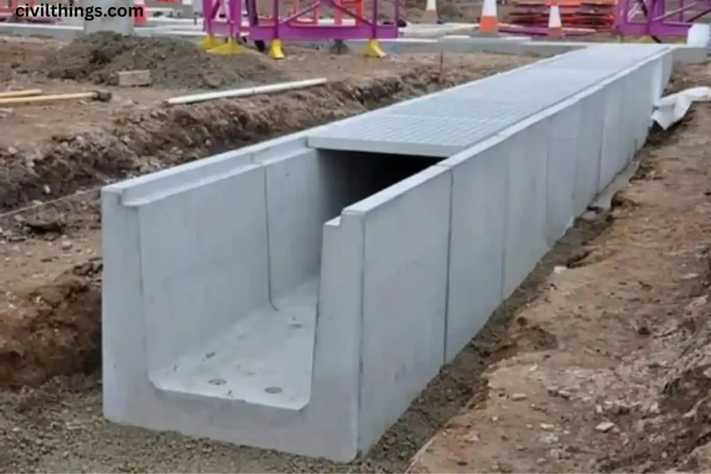
The term box culvert means a rectangular-shaped concrete structure built under roadways, railways, or embankments to allow water passage. It typically consists of a rigid frame (slab and walls) constructed with reinforced concrete. Unlike pipe culverts, it has a box-like structure and is highly stable, making it suitable for a wide range of applications.
Types of Box Culvert
There are several types of box culvert based on usage, size, and structural design:
- Single-cell box culvert – One rectangular passage.
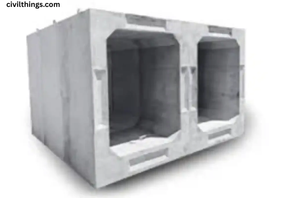
- Multi-cell box culvert – Two or more parallel rectangular passages.
- Precast box culvert – Constructed in a factory and transported to the site.
- Cast-in-situ box culvert – Constructed on-site with formwork.
- Rigid frame culvert – Designed to resist heavy loads and external pressures.
Uses of Box Culvert
The uses of box culvert are diverse in infrastructure projects:
- Drainage of rainwater and stormwater.
- Crossing small rivers or streams under highways or railways.
- Providing pathways for irrigation channels.
- Pedestrian or cattle underpasses.
- Supporting flood management systems.
Pros of Box Culvert
There are several pros of box culvert that make it widely adopted:
- Strong and durable due to reinforced concrete.
- Simple construction compared to bridges.
- Requires less maintenance.
- Can be precast, saving time during installation.
- Efficient for shallow flow and high discharge capacity.
Construction of Box Culvert
The construction of box culvert involves:
- Excavation – Digging the earth where the culvert will be placed.
- Foundation – Preparing a strong concrete base.
- Reinforcement – Placing steel bars for strength.
- Formwork – Installing shutters to shape walls and slabs.
- Concreting – Pouring reinforced concrete to form the structure.
- Curing and Finishing – Ensuring strength development and surface finishing.
Box Culvert Design and Detailing
The box culvert design and detailing include structural calculations for load, water pressure, soil resistance, and durability. Engineers ensure it can withstand traffic loads and water discharge. Proper reinforcement, slab thickness, and wall design are critical.
Box Culvert Installation
The box culvert installation process varies with precast or cast-in-situ methods. Precast units are placed with cranes, while in-situ requires on-site casting. Backfilling around the culvert ensures stability.
Box Culvert Bridge
In some cases, a culvert functions as a small bridge. A box culvert bridge is designed to carry heavy vehicular loads while allowing water to flow underneath. It is often used on highways and railways.
Box Culvert Drawing
Engineers prepare box culvert drawing plans that include layout, reinforcement details, and sectional views. These technical drawings guide the construction team.
Box Culvert Wing Wall Drawing
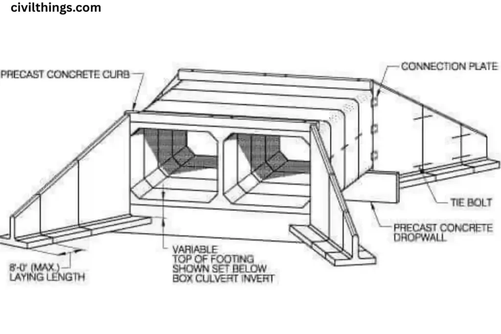
The box culvert wing wall drawing shows the retaining walls constructed on both sides of the culvert. These walls prevent soil erosion and direct water flow.
Engineering Type Drawing for Box Culvert
An engineering type drawing for box culvert provides detailed information, including dimensions, reinforcement layout, slab thickness, and load-bearing design. These drawings are essential for accurate execution.
Steps for Box Culvert Estimation
1. Earthwork (Excavation & Backfilling)
- Calculate the excavation volume for the foundation trench. Excavation Volume=Length×Breadth×DepthExcavation\ Volume = Length \times Breadth \times DepthExcavation Volume=Length×Breadth×Depth
- Deduct the box culvert’s external volume to get net backfilling.
2. Concrete Quantity
A box culvert has 3 main parts:
- Slab (Top & Bottom)
- Side Walls
- Wing walls / Aprons (if applicable)
For each component: Concrete Volume=Length×Breadth×ThicknessConcrete\ Volume = Length \times Breadth \times ThicknessConcrete Volume=Length×Breadth×Thickness
Then add all to get total concrete volume.
3. Reinforcement Steel
Steel is usually taken as 2–3% of RCC concrete volume (approximation if detailing not provided). Steel Weight=Concrete Volume×%Steel×Density of SteelSteel\ Weight = Concrete\ Volume \times \%Steel \times Density\ of\ SteelSteel Weight=Concrete Volume×%Steel×Density of Steel
where density of steel = 7850 kg/m³.
4. Formwork
Formwork area = Exposed surface area of all concrete members (slabs, walls). Formwork Area=Perimeter×Height×LengthFormwork\ Area = Perimeter \times Height \times LengthFormwork Area=Perimeter×Height×Length
5. Wing Walls / Head Walls
- Calculate separately as vertical RCC/stone masonry walls.
Volume=Thickness×Height×LengthVolume = Thickness \times Height \times LengthVolume=Thickness×Height×Length
6. Rate Analysis / Costing
After quantities are found:
- Multiply excavation (m³) × excavation rate.
- Multiply concrete volume (m³) × RCC rate.
- Multiply steel weight (kg) × steel rate.
- Multiply formwork area (m²) × shuttering rate.
- Add labor, machinery, and miscellaneous charges.
✅ Final Estimate = Earthwork + Concrete + Reinforcement + Formwork + Miscellaneous items.
📌 Example
Suppose we have a single-cell box culvert:
- Length = 5 m
- Internal span = 3 m
- Internal height = 3 m
- Wall thickness = 0.3 m
- Slab thickness = 0.4 m
Step 1 – Bottom Slab Concrete: V=Length×(Width+2×Wall Thickness)×Slab Thickness=5×(3+0.6)×0.4=7.2 m3V = Length \times (Width + 2 \times Wall\ Thickness) \times Slab\ Thickness = 5 \times (3 + 0.6) \times 0.4 = 7.2\ m^3V=Length×(Width+2×Wall Thickness)×Slab Thickness=5×(3+0.6)×0.4=7.2 m3
Step 2 – Top Slab Concrete:
Same as bottom slab → 7.2 m³
Step 3 – Walls Concrete: V=2×(Height×Thickness×Length)=2×(3×0.3×5)=9 m3V = 2 \times (Height \times Thickness \times Length) = 2 \times (3 \times 0.3 \times 5) = 9\ m^3V=2×(Height×Thickness×Length)=2×(3×0.3×5)=9 m3
Total Concrete = 7.2 + 7.2 + 9 = 23.4 m³
Reinforcement (say 2%): Steel=23.4×0.02×7850=3675 kgSteel = 23.4 \times 0.02 \times 7850 = 3675\ kgSteel=23.4×0.02×7850=3675 kg
Formwork = exposed surface area ≈ 100 m² (approx).
Conclusion
The box culvert is one of the most essential civil engineering structures that ensures smooth water flow, prevents flooding, and supports transportation systems. From understanding box culvert means to exploring types of box culvert, its uses of box culvert, construction of box culvert, and detailed drawings, it is clear that this structure offers both durability and versatility. Whether applied as a box culvert bridge or drainage solution, its adaptability makes it indispensable in modern infrastructure.

Hello! I’m Vaishnavi, a civil engineer who enjoys sharing how we design and build structures. My blog makes understanding engineering easy and interesting for everyone!